-
1) The Concept of Spring Analysis
-
2) Example & Tutorial
-
3) Comparison of Results
8. Spring
In this lecture, We will learn about the concepts, principles, and behavior of the structure having spring support. Besides this, we will learn about the various boundary springs available in midas Civil. And then, We will compare the results of deflection of the frame having two different models (one with internal hinge and the other with spring) using midas Civil.
Chapter 1) The Concept of spring analysis
- Introduction to spring/ Elastic boundary elements
- Details of surface spring support
- Concept of spring
Chapter 2 ) Example
- Modelling, boundary condition setting, applying load using Midas Civil.
- Analysis and compare the results for the frame having two different models (one with internal hinge and the other with spring) using Midas Civil.
Chapter 3) Comparison of Results
- Comparison of Deflection and forces in members.
Summary
Elastic boundary elements or springs are mainly used when considering the stiffness of adjacent structures or ground located at the boundary of a model, or when elements lacking degrees of freedom (truss, plane stress, plate elements, etc.) are mutually connected.
It is possible to input 6 degrees of freedom (3 components in the linear direction and 3 components in the rotational direction) based on the global coordinate system per arbitrary node. In addition, the elastic component in the linear direction is input in units of force per unit length, and the elastic component in the rotational direction is input in units of moment per unit angle (radian).
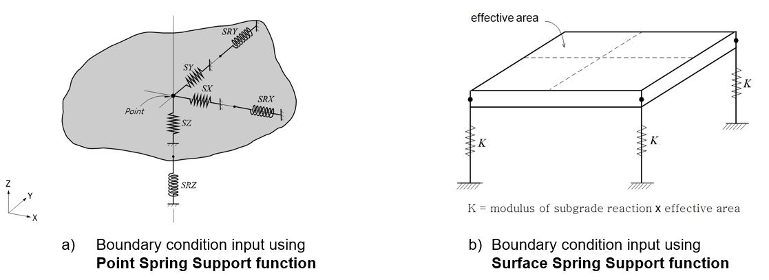
The elastic boundary element is useful for reflecting the column or pile under the structure to be analyzed or the ground stiffness.
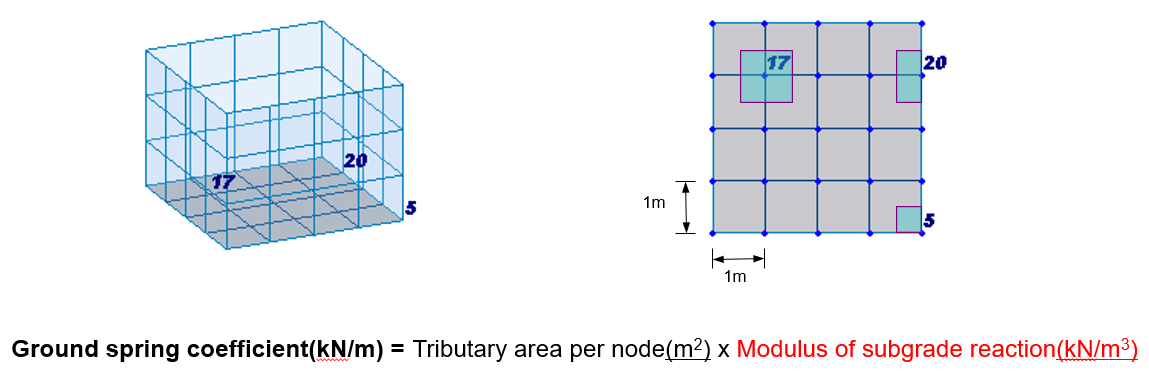
When modelling the ground, the value obtained by multiplying the modulus of subgrade reaction by the tributary area of the corresponding node is used.
At this time, care must be taken because the characteristics of soil are effective for compression, but cannot resist tensile force. (Compression Only Type Spring)
In the case of considering the axial stiffness component of the column or pile in contact with the target structure, the stiffness of the elastic boundary element can be calculated as EA/H.
Here, E is the modulus of elasticity of the support member, A is the effective section area, and H is the effective length.
The elastic component in the rotational direction is mainly used to reflect the rotational stiffness of the adjacent boundary of the structure to be analyzed, and is determined by the value of α EI/H when the adjacent boundary is a column.
where α is the rotational stiffness component factor determined by the connection state of the column, I is the effective area moment of inertia, and H is the effective length of the column.
Boundary springs used for nodes are generally input for each degree of freedom direction, but for precise analysis, stiffness coupled with other degrees of freedom must be considered.
That is, in order to consider the rotational displacement that occurs simultaneously when the movement displacement occurs, it is necessary to input the spring considering the related stiffness.
For example, when modeling a pile for the foundation of a structure uses boundary spring, the more precise analysis can be performed by additionally inputting the related stiffness in addition to the stiffness in each direction.
Boundary springs input to the nodes generally follow the global coordinate system, but when the nodal coordinate system is used for the nodes, they follow the nodal coordinate system (Node Local Axis).
In the analysis step, when there is no stiffness component for a specific degree of freedom after combining the stiffness matrix, a very small value is used for the rotational elasticity component to avoid a singular error that may occur.
Although there is a difference depending on the unit system used, a value of 0.0001 ~ 0.001 is mainly used.
To prevent such singularity errors, midas Civil has a built-in function that automatically assigns rigidity to the extent that it has little effect on the analysis results.
- MIDAS Members My profile Sign up

© MIDAS IT Co., Ltd.