-
1) What is Continuous Beam?
-
2) The Concept of Continuous Beam Analysis ?
-
3) Example & Tutorial
-
4) Comparison of Results
5. Continuous Beam
In this lecture, We will learn about the concepts, principles, and behaviour of continuous beams. We will also learn the concepts of indeterminacy in structure and how to analyse it. And then, We will compare the results like BMD and deflection, of the continuous beam having different boundary conditions using midas Civil.
Chapter 1) What is a continuous beam?
- Introduction to continuous beam.
- Description to determinate and indeterminate structure.
Chapter 2) The concepts of Continues beam analysis.
- Structural behaviour of the continuous beam
- Solution for indeterminate structure
Chapter 3) Example
- Modelling, boundary condition setting, applying load using Midas Civil.
- Analysis and compare the results for the continuous beam having different boundary conditions.
Chapter 4) Comparison of results
- Brief description to Moment distribution method.
- Comparison of Deflection, shear forces, and moment in members.
Summary
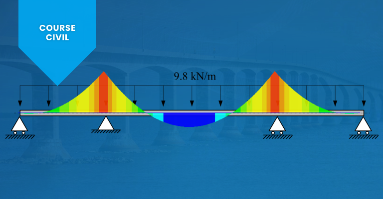
A structure consisting of two or more simple beams connected in a row is called a continuous beam.
In a continuous beam, the number of unknown reactions or forces is greater than the number of equilibrium equations, resulting in an indeterminate structure.
While the reactions of a determinate structure can be determined solely by equilibrium equations, additional conditions such as compatibility of deformations are necessary for an indeterminate structure like a continuous beam.

The structural behavior of a continuous beam is influenced by the beam flexural stiffness of adjacent spans.
In a three-span continuous beam as shown in figure above, the moment distribution on span BC varies depending on the beam flexural stiffness characteristics of adjacent spans AB and CD.
If beam BC is a simple beam, then the moment at both ends (B and C) should be zero.
However, due to adjacent beams, end moments (𝑀𝐵 and 𝑀𝐶) will occur.
The magnitude of 𝑀𝐵 and 𝑀𝐶 varies depending on the beam flexural stiffness of spans AB and CD.
Since the flexural stiffness of span AB, where the rotation at end A is restrained, is greater than that of span CD, where the rotation at end D is not restrained, 𝑀𝐵 becomes greater than 𝑀𝐶.

As shown in Figure 5.2, the moments M1, M2, M3, and M4 required to induce a unit rotation at the left end depend on the conditions at the right end.
Figure 5.2(a) represents the case where the right end is fixed, while Figure 5.2(b) represents the case where the right end is a hinge.
Figure 5.2(c) shows a shape that is symmetric with respect to the centerline due to the same unit rotation (1) occurring at the right end, while Figure 5.2(d) shows a shape that is symmetric with respect to the centerline due to the opposite unit rotation (-1) occurring at the right end.
As a result, the beam stiffness is in the order of magnitude is Figure 5.2(c) (6EI/ℓ), Figure 5.2(a) (4EI/ℓ), Figure 5.2(b) (3EI/ℓ), and Figure 5.2(d) (2EI/ℓ).
- MIDAS Members My profile Sign up

© MIDAS IT Co., Ltd.