-
1) What is Shear Stress ?
-
2) Example
-
3) Comparison of Results

6. Shear Stress
In this lecture, We will learn about the concepts and principles of Shear stress of soil. Then we will discuss the various parameters to determine the shear stress. We will also discuss the field method to determine the shear stress of soil. Moreover, In order to comprehend the soil shear stress utilizing GTS NX software, we will simulate the triaxial test with different drained conditions of the soil. The findings will be compared with those obtained manually and using the program.
Chapter 1) What Is Shear Stress
- Introduction to shear Stress.
- various parameters to determine the shear stress.
- field method to determine the shear stress
Chapter 2) Example
- Modelling, boundary condition setting, applying load using Midas GTS NX software to simulate the Triaxial test.
- analysis and see the results for the same.
Chapter 3) Comparison of results.
- Compare the results with those obtained manually and using the program.
Summary
1. Concept of shear strength
When significant deformation occurs in the ground to the point where its functionality is lost, this is referred to as collapse.
Failure occurs when the induced shear stress exceeds the shear strength.
Such failure behavior cannot be considered in elasticity theory.

In order to define the state of ground failure, failure criteria are used.
The most widely used criterion is the Mohr-Coulomb (MC) failure criterion.
The Mohr-Coulomb failure criterion is a maximum shear stress theory, which means that failure occurs due to slipping or shearing between particles, that constitute the material, due to the maximum shear stress.

2. Mohr-Coulomb Shear Strength Theory
The Mohr-Coulomb theory, which is the maximum shear strength theory, can be considered through the behaviour of friction blocks. Let's look at the case where the vertical force N is applied to the block and the lateral force F is applied to move it by simulating the shear behaviour between particles in the ground as shown in (a) of Figure 6.3.
The block starts to move when the force F exceeds the friction resistance of the floor. The movement of the block can be seen as a shear failure.
If we apply different values of N and calculate the corresponding F value for the block to move, the relationship between F and N is usually represented as a straight line, as shown in Figure 6.3(b).

The line defines the criterion for the boundary between the stable state and the failure state, in other words, the failure criterion.
If we denote the equation of this line as F=𝜇N, the slope 𝜇 represents the coefficient of friction.
The coefficient of friction is usually expressed as 𝜇=tan ∅𝜇′ using the slope ∅𝜇′ of the line.
Therefore, F=N tan ∅𝜇′.
If the contact area is A, then 𝜏=F/A and 𝜎𝑛′=N/A
So 𝜏𝑓 = 𝜎𝑛′ tan ∅𝜇′.
In real soil, strength exists even when the vertical stress (effective stress) is zero, due to the presence of tensile strength in the fracture plane, i.e., true cohesion, 𝑐^′.
Since adhesion also constitutes shear strength, the shear strength expression that defines failure can be expressed as follows :

In the case of dilatancy, such as over-consolidated soil, the shear strength can be expressed using dilatancy angle (𝜑) as follows :

The shear strength is a function of the cohesion force (𝑐′), internal friction angle (∅′), and dilatation angle (𝜑), which are the properties of the ground material, and is proportional to the size of the normal stress (𝑛𝜎′).
The parameters used for stress–strain analysis are obtained from the effective stress relationship.
The reason is that the stress that affects the deformation of the ground is not total stress, but effective stress.
3. Shear Test and Strength Parameters Determination
The strength parameters 𝑐^′ and ∅^′ define the shear strength of the MC destruction standard.
The shear strength parameter can be obtained through the shear test.
The direct shear test and the triaxial test are typical shear tests.
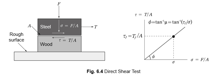
(1) Direct Shear Test
The concept of the direct shear test is illustrated in Figure 6.4.
It is a test that involves destroying the specimen along a predetermined shear plane, rather than the failure plane being determined by the stress state.
Figures 6.5 and 6.6 show the results of Direct shear tests of sand and clay, respectively.
The shear strength parameters can be determined from the relationship between the confinement stress (𝜎′) and the shear stress at failure (𝜏𝑓).
As the stress conditions determine the actual failure plane of soil, so there may be differences between the results of direct shear tests, in which the failure plane is predetermined and sheared directly.

- MIDAS Members My profile Sign up

© MIDAS IT Co., Ltd.